Porcelain Insulator News
by Elton Gish, NIA #41
Reprinted from "Crown Jewels of the Wire", November 1984, page 22
This month I want to temporarily deviate from the usual question/answer
format or discussion of individual insulators. This change is partly due to few
new reports and/or interesting questions. This is your forum, and we need to
hear from you.
A recent trip to a local university library produced several
informative articles that I thought would be of interest to many of you.
This
article is from the December 3, 1904 issue of ELECTRICAL WORLD and ENGINEER and
is based on a professional paper presented by Mr. V. G. Converse, whose name all
of you should recognize. While the article may be too detailed for some, it does
present a historical sequence in "The Evolution of High-Tension
Insulators".
The Evolution of High-Tension Insulators.
In a paper read before the recent International Electrical Congress, Mr. V.
G. Converse gave an interesting account of the evolution of the present types of
high-tension insulators. In 1890 the first alternating-current power
transmission in the United States used for 3,000 volts a glass insulator of the
form shown in Fig. 1. This is an insulator such as is commonly used by the
telegraph companies, and is only about 3 in. in diameter. In spite of the
predictions that the insulator would not suffice, the plant continued in
operation for six years without insulator troubles.
For the famous Frankfort-Lauffen transmission experiments in Germany in 1891,
a porcelain insulator with an oil cup was used. No definite information as to
the exact shape of this insulator is at hand, but the principle was probably not
unlike that of the insulator shown in Fig. 2. Voltages as high as 28,000 to
30,000 were used in these experiments for a limited time. Insulators with oil
cups of various forms appeared very shortly afterward in England and the United
States. If the insulator was of glass the outer petticoat was usually curved
inward and up so as to form an internal groove which would hold oil. A common
form for porcelain insulators was to bring down a petticoat from the body of the
insulator which would dip into a cup of oil, the cup being made in a circular
form and held in place around the pin by a support on the pin. Insulators with
detachable oil cups were supplied for the 10,000-volt transmission at Pomona and
San Bernardino, Cal, .started in 1892. The oil cups were not used, however, as
they were found to be unnecessary.
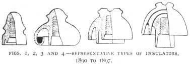
Insulators without oil cups being equally effective as those with oil cups, a
form similar to that shown in Fig. 3, made of either glass or porcelain came
into use. Here the idea was to impede the leakage of current over the surface by
introducing petticoats which gave a very long surface between the conductor and
the pin. Some insulators had as many as four or five such petticoats.
No further increase in voltage is noted until 1895, when we find the
Hochfelden-Oerlikon transmission in Switzerland at 13,000 volts. In 1897 we had
transmissions in the United States at 16,000 volts.
About this time it was found that porcelain insulators which had been formed
and pressed in iron moulds had not a sufficiently compact or homogeneous
structure and were apt to be punctured in service. A study of the matter showed
that really the only effective dielectric insulation of the porcelain was
contained in the glaze over the surface of the porcelain. In some cases it was
found that the interior body of the porcelain insulator would actually absorb
and hold a considerable quantity of water. The manufacture of porcelain was then
studied with a view to overcoming these difficulties. The method was resorted to
of making the insulator in several thin shells which were glazed separately and
then glazed and fired together, the potter's wheel being reverted to in order to
make the shells of sufficient compactness. This construction is shown in Fig. 4.
It will be noted that a petticoat is here extended down for a distance over the
pin for the purpose of further insulating from the pin. Attempts have been made
heretofore to extend a petticoat down around the pin, but when the insulator was
made in a mould no such long petticoat could be made as is now possible when the
insulator is made in several parts.
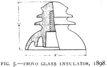
In 1898 we have the first commercial very high voltage plant in operation in
the United States, at Provo, Utah. This transmission is at 40,000 volts. The
insulator used is of glass, shown in Fig. 5. This insulator has outwardly
extending petticoats, the purpose of these petticoats being to provide unexposed
surfaces near the wire in order to prevent surface leakage.
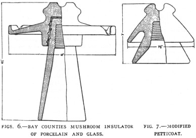
In 1900 the demands of the Bay Counties and Standard Electric Companies of
California, for 60,000 volts, made necessary a very much larger insulator than
had ever been made before, shown in Fig. 6. In this insulator the outer
petticoat is carried out almost horizontally, and a gutter is formed on the top
near the edge of the petticoat to conduct water away from the cross arm. The top
piece of this insulator was originally of porcelain, and the petticoat around
the pin, which now amounts to a sleeve extending down the whole length of the
pin, was of glass, the glass and porcelain being secured together by sulphur at
first and then cement. This type of insulator has been commonly designated the
"mushroom" type, from its appearance.
A modification of the outwardly extending petticoat idea is seen in the
insulator shown in Fig. 7. This form has had a limited use.
While the insulators enumerated have been referred to in order to show the
successive steps in the development of the present highest-tension insulators,
it must be understood that such insulators are not still in use. On the
contrary, with the exception of the oil insulator, all of these types and many
others possessing the same essential characteristics, are in service, at the
various voltages for which they have been found adapted. Even the telegraph
insulator shown in Fig. 1 has shown good service in certain localities at
voltages as high as 10,000.
Insulators of the types 3, 4, 5 and 6 are in use for voltages as high as
40,000. In various sizes these same insulators are used for all intermediate
voltages up to 40,000. Types 5 and 6 are in use in a few cases at 45,000 volts.
Some of these insulators have given good service from the first, while others
have failed. It is believed that the failures have been largely due to faulty
material. In some cases it has been necessary to replace a whole equipment of
insulators because of their faulty construction; in other cases a gradual
weeding out has been necessary until the faulty insulators were removed.
Occasionally we hear of a plant operating where there has been almost no trouble
with insulators, except with such as have been broken by outside interference.
In general it is believed that the feeling exists that the line insulator
problem for voltages as high as 40,000 has been satisfactorily solved.
We are now to the point of consideration of the very highest-voltage
insulators -- those which are in use for voltages from 50,000 to 60,000. Fig. 8
shows a glass insulator used by the Missouri River Power Company in Montana, for
55,000 volts. This insulator has been in service since 1901. The insulator is in
two parts, one a hood 9 in. in diameter, and the other a sleeve set over a pin.
The sleeve which is open at the top adds nothing to the dielectric strength of
the insulator, its purpose being to protect the wooden pin. Obviously the sleeve
would be of little value if a metal pin were used. This type of insulator
possesses the advantage of being in two parts, which are separable, either of
which can be replaced if broken.
The insulator used for the 50,000-volt transmission at Shawinigan Falls,
Que., is shown in Fig. 9. This is of porcelain and made in sections. Each
section has a closed top and adds to the dielectric strength of the insulator.
Two petticoats, one 9 in. and the other 10 in. in diameter, extend outward and
give the effect of one insulator over another. One section extends down around
the wooden pin and serves to protect the pin. The sections are held together
with Portland cement. This insulator shows the combination of the sleeve around
the pin, outwardly extending petticoats and of sections, as first indicated in
Figs. 4 and 5.
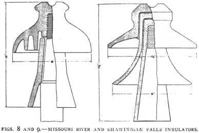
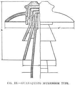
Fig. 10 shows a very large and extended form of the mushroom type, which has
recently been put into use on the 60,000-volt transmission at Guanajuato,
Mexico. The top section is 14 in. in diameter. The sections are secured together
with Portland cement, and the whole is cemented to a hollow metal pin.
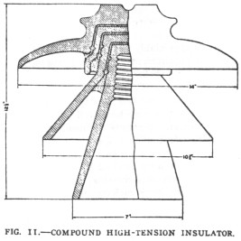
For several transmissions under construction for voltages between 50,000 and
60,000, the insulator shown in Fig. 11 has been adopted. Some of these
insulators exceed 14 in. in diameter and weigh as much as 25 pounds.
Abroad insulators are used which are similar to those used in this country.
It is probable, however, that they have not been made in such large sizes, also
that corresponding sizes are used for lower voltages.
The present highest-voltage insulators, then, of which the writer knows, and
which may be considered as representing the most advanced state of the art in
insulator design and construction, are represented by Figs. 8, 9, 10 and 11.
Whatever advantage one may possess over the others will doubtless be shown in
course of time.
Mr. Converse gave the following requirements for a high-tension insulator:
- The material must have a high dielectric strength; in other words, it must
be strong to resist puncture by the current. In order to fulfill this
condition, the material must be continuous, compact and homogeneous, even
the most minute crack or fracture being a weakness.
- There must be sufficient resistance over the surface of the insulator so
that there will be no considerable conduction or leakage of current.
- The distance around the insulator between the wire and the pin or support
must be sufficient to prevent the current from arcing.
- The second and third requirements are dependent upon the shape of the
insulator. Its contour must be such that there will be unexposed surfaces
which will not get wet or accumulate dirt, salt, etc., as these materials
are conducive to leakage and tend to lessen the arcing distance. Evidently
the requirements which are dependent upon climatic conditions vary with the
locality in which the insulators are to be used. If in a country which is
not subjected to heavy rains, sleet or dust storms, the insulator may
perhaps be smaller than an insulator required in a locality where the
climatic conditions are severe. Usually a larger type of insulator is
required for the same voltage in a cold country than in a warmer climate.
This may explain why some insulators which have been very satisfactory under
a given voltage in one locality have utterly failed when tried at the same
voltage in another place. In some localities, particularly on the Pacific
Coast, the accumulation of salt is so great from the so-called salt fogs
that it has been found necessary to have the unexposed surfaces rather
shallow and with few petticoats in order that the surfaces may be readily
accessible for periodical cleaning.
- The shape and arrangement of the petticoats should be such that the
electrostatic capacity of the insulator will be small.
- The internal heat losses from conduction and hysteresis should not be such
as to appreciably heat the insulator.
- Mechanical requirements, such as strength, mounting, method of fastening
the wire, color, etc., are in general dependent upon the conditions to be
met. It does not seem as if details like gutters, spouts, drip points and
the like can be considered of much value. They are features which may look
well in theory, but can cut but little figure in practice. Certainly the
insulation of our high-voltage lines is more dependent upon a good, strong
insulator with liberal margins of safety, than upon such refinements.
The following tests were advised in order to determine whether insulators
will meet the requirements:
1. In order to determine dielectric strength, porcelain insulators should be
inverted, with their heads dipping into salt water, the solution extending well
over the head of the insulator. The hole for the pin should also be filled with
salt water. The predetermined voltage for testing may then he applied to the two
salt solutions Usually a voltage test of several minutes is made. The defective
insulators will be punctured in this manner. If the porcelain insulators are
made in several sections, the purpose of the sections being to obtain greater
dielectric strength, then the sections should be tested individually in the same
way. When the sections are cemented or assembled to complete the insulator, it
is advised to again test, using the same method, in order to be certain that the
sections have not been broken. Every porcelain insulator of a lot should be
tested in this manner.
If the insulators are of glass it is best to have every insulator tested ill
the manner described for porcelain insulators, but as the defects in glass are
easily visible it may be only necessary to test a few of a lot in order to
determine the strength of the glass, the remainder passing the rigid examination
of an inspector who will discard such insulators as have cracks, air bubbles or
less than the required thickness.
2. The measurement of leakage over the surface of an insulator is an
extremely difficult thing to accomplish and the refined methods which are
required are not applicable to factory tests of a large number of insulators.
Any leakage of account will be observed in the test for dielectric strength,
either by the visible creepage of the current over the surface or by the heating
of the insulator.
3. A lot of insulators having passed a preliminary inspection, it is only
necessary to test a few in order to meet the third requirement. These may be set
up as if in service and the predetermined voltage applied. It is customary to
apply the voltage to the line and pin. It is further advised that a voltage be
applied across two insulators mounted in the same way, in order to duplicate as
near as possible normal running conditions.
4. In order to test for the effectiveness of the contour of an insulator, it
is necessary to imitate as nearly as possible the most severe climatic
conditions under which the insulator is to operate. Tests of this kind have not
been extended farther than to obtain the effect of a heavy driving rain. An
insulator mounted as for use should have a broken spray of water thrown upon it
at an angle but slightly above the horizontal. The results with this combination
may then be noted with a predetermined voltage applied between line, and pin, or
between two insulators similarly treated.
The electrical requirements of a high-tension insulator are at variance with
the requirements for mechanical strength in the following respects:
1. In order to increase the dielectric strength, reduce the capacity and
lessen the brush discharges, it is necessary to increase the thickness of the
head of the insulator. As the thickness is increased, the pin or support in the
insulator is removed farther from the strains of the wire and mechanical
stresses are brought upon the insulating material which it is incapable of
withstanding. Especially is this true if the wire is tied or supported on the
top of the insulator.
2. If the point of support of the wire is lowered to the side of the
insulator, it is necessary that the insulator be of large diameter at the point
of support in order to have the required dielectric thickness. Also with the
wire on the side of the insulator, the surface distance is decreased and the
length of the adjacent petticoat must be correspondingly increased.
3. No logical or safe arrangement has ever been proposed whereby all the
lines of a circuit can be supported otherwise than on the tops of the
insulators. In this position the surface of the insulator is exposed to the
elements, at least as far as the edge of the extending petticoat adjacent to the
line, and the effect is to aggravate the cause for leakage for a certain
distance, where it must be checked.
4. The requirement for a larger insulator means one which is more breakable
-- if of glass, one apparently beyond the present knowledge of how to mould, or
how to anneal.
The electrical requirements are also contradictory in this respect --a larger
insulator for increasing the arcing distance adds but little resistance to
leakage and probably increases the capacity.
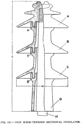
Mr. Converse stated that he early foresaw the objections to making insulators
of constantly increasing diameters for increasing voltages, and proposed the
making of insulators in parts and with outwardly extending petticoats. Such
construction is shown in Fig. 12. Other forms of insulators embracing the
essential features have been already shown, as in Figs. 9 and 11. The purpose of
the construction of the insulator shown in Fig. 12 was to study the effect of
the outwardly extending petticoats in resisting arcing of the current between
line and pin. The exact details of construction are a top piece, A, screwed onto
a wooden pin, H; the two like sections, B and C, and a supporting section, D,
resting on the cross arm or support, and holding B and C. D also serves the
purpose of protecting the pin. The grooves at e, f and g are for holding an
insulating medium, if desirable to insulate between the several parts. These
parts being readily separable, it is easy to assemble A and D, or A, D and
either B or C. Sections A, B and C were 10-1/2 in. in diameter. Under test the
terminals of the testing apparatus being connected at the point for the wire and
at the cross arm, the current arced around at the following voltages, with the
insulator clean and dry: A and D, 144 kilovolts; A, B and D, 186 kilovolts; A,
B, C and D, 225.
Under a spray of water at 45 degrees precipitation three-fourths of an inch
in five minutes, the current arced at the following voltages: A and D, 118
kilovolts; A, B and D, 157 kilovolts; A, B, C and D, 198 kilovolts.
No insulating material was used in the grooves during these tests.
There was no tendency for the current to arc between the sections, and there
were no serious discharges up the inside of the sections or in the grooves
between the sections. This experiment is considered of importance in that the
addition of each outwardly extending petticoat section requires a nearly equal
additional voltage to produce arcing. The advantage of a properly proportioned
insulator with outwardly extending petticoats is, evidently, less diameter for
the same resistance to arcing around than an insulator of the mushroom type.
As to the surface conditions on insulators of glass and porcelain, no
differences have been noted in the conduction or leakage of current. With high
tensions, such as water or moisture as falls on the insulator is quickly
dispelled or dried off by the leakage of current, high tensions tending always
to keep an insulator dry. In general losses on high-tension insulators, until a
brush appears, are so small that they are negligible. With the brush the losses
increase very rapidly with increase in tension.
|

)
)
)
)
)
)
)